

Spring Loaded Relief Valve Details: Valve Internals
A spring loaded relief valve is used in many applications to protect the over pressurization of vessels, pipes and containers. Conventional and balanced bellows relief valves are examples of spring loaded relief valves. Codes and standards like ASME, API,and ISO (to name a few) require that these relief valves are sized to have a relieving capacity that is sufficient to maintain the integrity of the system by preventing the internal pressure for exceeding the design limits. In general, the relief valve is designed and selected by the relief systems designer to meet process-engineering requirements.
Relief Valve Stability:
A spring-loaded relief valve can be thought of as a spring /mass system which is why relief valves chatter. Researchers have found significant differences in the stability of relief valves based on the design of their internals. One recent study found that with 6 feet of inlet piping, valves from Manufacturer X were stable in 50% of the tests while valves from Manufacturer Z where stable in 100% of these tests.¹ Smith & Burgess Laboratory research has confirmed these findings. However, relief systems designers tend to downplay (if not ignore) the importance of the mechanical design of relief valves which is important to stability. Therefore, this article discusses the fundamentals of the design parameters for the internals of a relief valve. The intent is to provide design considerations and general operation information for use by relief systems designers, specifically assisting with the understanding of the effects of valve design on stability.
Relief Valve Internals:
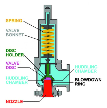
Modern relief valves are wonderfully modular.The internal parts for a relief valve (valve disc, disc holder, blowdown ring and spring) can be interchanged for ones with a different design to customize valve performance based on the application, fluid service, and set pressure. Valve disc can be metal-to-metal or soft seats. Soft seat designs use an elastomer to create a better seal between the valve disc and the nozzle. Relief valves with elastomer seats have limitations and can only be used in certain applications. Disc holders are generally designed to allow the valve disc to float which provides an angular movement that reduces seat leakage from minor misalignments (ensuring that the valve disc has 360 degrees of contact with the nozzle). The disc holder outside diameter, shape and thickness plays an important role in determining the valve performance by defining the shape of the huddling chamber. The huddling chamber can also be defined by the blowdown ring(s). The ring(s) can also be swapped to different sized and shaped rings to adjust performance based on the expected relief fluid. Springs are selected to keep the valve closed and must fit inside the valve bonnet. The force the spring exerts is an important design criteria for a relief device and varies depending on the relief fluid, valve size and set pressure.
Pop Action:
Spring loaded relief valves are known as "pop action" relief valves as they typically pop open at their set pressure. Initially, the pressure differential across the valve disc that creates the force to over come the spring force and open the valve.The pop action occurs because most huddling chambers are designed with an area that is approximately 10%-30% larger than the valve seat (as the disc holder is bigger than the valve disc). Once the pressure under the seat is enough to lift the valve disc off the nozzle, there is a step change in the upward forces on the spring and the valve "pops" open. The shape of the huddling chamber (created by the shape and size of the disc holder), the position and shape of the blowdown ring, and the characteristics of the fluid being relieved together determine the initial opening force and the initial lift of the valve.
Adjustable Blowdown Rings:
Blowdown rings are adjustable rings with a design shape that modifies the effluent flow path and huddling chamber based on the position. For process valves, a single blowdown ring is typically threaded onto the nozzle and can be adjusted vertically up or down. Manufacturers will specify a recommended position relative to contact with the valve disc. The position of the blowdown ring is fixed with a locking screw. The position of the blowdown ring changes the blowdown (or reseat) pressure. For valves with a single blowdown ring, the closer the blowdown ring is to the nozzle, the lower the pressure in the system will need to be for the valve to close (more blowdown). Other relief valves have multiple blowdown rings. Each manufacturer designs a unique blowdown ring to compliment other aspects of the relief valve design. Smith & Burgess' testing confirms that position and design of blowdown ring(s) affects valve stability.
Spring Selection:
Relief Valve manufactures generally select a spring that is designed for the set pressure of the valve. The spring that is selected will have a pressure range that the spring can be applied. In many cases, there may be more than one spring that can be used with each relief valve each having a different spring constant. The stiffer spring may have a range that is higher than the softer spring but still meet the overall requirements for set pressure. The selection of the spring will affect stability as the specific spring influences the natural frequency of the valve and can also affect the blowdown.
Valve Moving Mass:
All relief valve manufactures have internal designs which differ in shape and size. This ultimately leads to differences in the mass of the moving components (valve disc, disc holder, and a portion of the spring). For two similarly sized relief valves with the same set pressure, the relief valve with higher moving mass will accelerate slower than one with less mass. Smith & Burgess testing has shown that relief valves with higher moving mass tend to be more stable. This is because there is an increase in the inertial effect that increases the damping of the valve. It should be noted that the impact forces when the valve does chatter where observed to be higher for a valve with more moving mass.
Compensation for Backpressure:
For spring loaded relief valves, when backpressure is present, the manufacture may recommend the addition of a bellows. This bellows is secured at one end to the backside of the disc holder and on the other end to the valve guide. In addition, when a bellows is installed, the plug in the valve bonnet is removed. Bellows reduces the effect of backpressure on the valve by isolating a portion of the disc holder and holding the pressure at atmospheric. By design, we add bellows to a relief valve to minimize the effects of backpresssure. To date, the affect that adding a bellows to a relief valve has on stability has not been tested. One concern with bellows is that they are thinly formed metal components that are prone to cracking (and leaking) due to both high and low cycle fatigue. In general, a bellow's fatigue life is approximately 500 – 1000 cycles. Additionally, the affect that adding a failed bellows has on stability has not been tested.
Conclusions:
The design of spring loaded relief valves differs from manufacturer to manufacturer. Each use proprietary internal designs to achieve similar capacity performance results. Stability, however, is valve specific and determined by each valves unique huddling chamber, spring rate, moving mass, guiding surface (L/d) and materials of construction. This post describes how the inter-working of the relief device affect the valve operation which subsequently affects valve stability. Further posts will more fully explore this topic.
References:
- 1. Darby, Ron, and A. A. Aldeeb. "The Dynamic Response of Pressure Relief Valves in Vapor or Gas Service. Part III: Model Validation."
Journal of Loss Prevention in the Process Industries 31 (2014): 133-141. - 2. Pentair Pressure Relief Valve Engineering Handbook: PVCMC-0296-US-1203rev 1-2015